Whoooo Hoooo .. back to the build.
Navigation
Install the app
How to install the app on iOS
Follow along with the video below to see how to install our site as a web app on your home screen.
Note: This feature may not be available in some browsers.
More options
You are using an out of date browser. It may not display this or other websites correctly.
You should upgrade or use an alternative browser.
You should upgrade or use an alternative browser.
SBS Project - Sportster Chop w/ Lots of Photo's
- Thread starter DK Custom Products
- Start date
TonkaDriver
450+ Posts
Picture gone
The picture disappeared. There was a picture of the clamp when I posted it. Sorry it didn't stay. I even previewed it.
Kurt
Thank you for the info on coil clamps!
Kevin
The picture disappeared. There was a picture of the clamp when I posted it. Sorry it didn't stay. I even previewed it.
Kurt
DK Custom Products
Sponsor
- Thread starter
- #183
This project started out with a bang. Excitement, on our part, was high. We had the time to work on it each week, and we made slow but steady progress.
The excitement level was high, with the thought of riding it not too far in the future a constant fuel to "get it done"!
For over a year we have been extremely short on time to dedicate to this project, and the bike has sat, largely ignored.
Every now and then we would have a few hours to spend on it. The hours we have spent, here and there, have been more out of obligation than excitement at getting it done. (since we knew that it might be another month or two before we could work on her again)
We have so many pressing projects, that we literally do not know when we will have the time to make this bike what we want it to be.
I still have the vision for it, am still looking forward to riding it, but it is with regret, but a realistic assessment of priorities, that we are setting this project aside indefinitely.
Rather than work on it in starts and stops, it will sit, lonely against the wall, under cover, until we have the time to finish it out quickly.
At some point, the time will be available, and the fire to get it done stronger than ever, and we'll get her done!
Kevin
DK Custom Products
Sponsor
- Thread starter
- #184
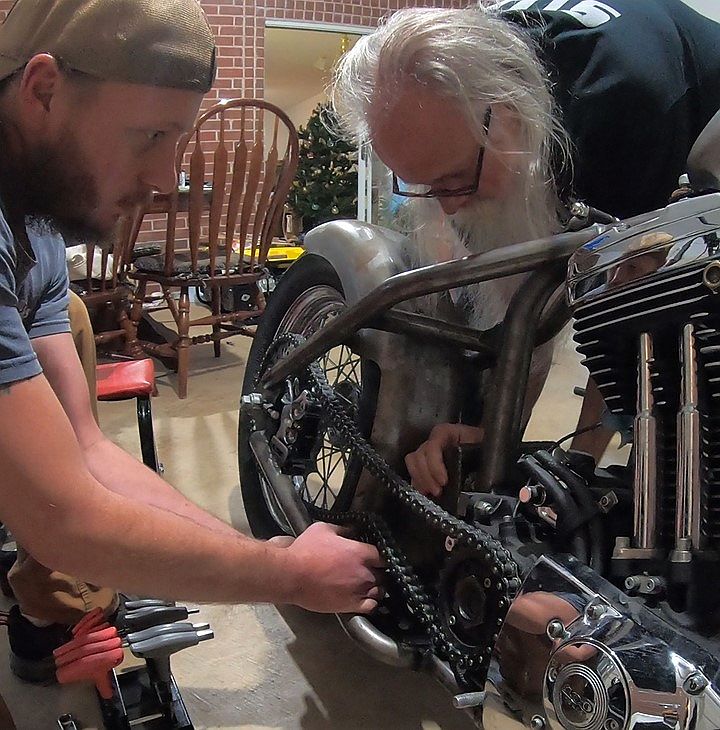
Devin and I sat down last Friday and started back on the SBS Chop!
Almost 2 years of her languishing in the corner, and she's about to start getting some attention again.*")
This week, we're looking at her with new eyes.
:clapping:
Kevin
Almost 2 years of her languishing in the corner, and she's about to start getting some attention again.*
This week, we're looking at her with new eyes.
:clapping:
Kevin
Whoooo Hoooo .. back to the build.
Ditto
DK Custom Products
Sponsor
- Thread starter
- #186
Ditto
Yeah! :laugh: False start over a year ago!
When we sat down to get back on this a week ago, our initial "to-do" list was 2 pages long. After sitting down with the bike, late last week, that list grew to over 3 pages.
There are so many balls to juggle on a build like this…
We’ve been away from the bike for well over a year, and getting back immersed in all the details has taken this last week.
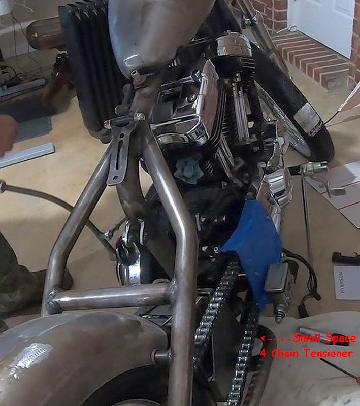
...one of (the many) things we are looking at is we have one small space, and we want/need/probably won’t be able to fit 4 things in this space-
- Part of the exhaust
- Rear brake MC
- Oil Tank/Battery Box
- Chain Tensioner
We’ll get it figured out. It takes time & some creativity, but we’ll get it done without compromising the vision of the build.
Some photos coming soon.
Kevin
DK Custom Products
Sponsor
- Thread starter
- #187
We are back full swing into this build!
Time is still short, but we have a lot of motivation, so we're making the time!
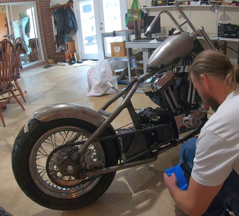
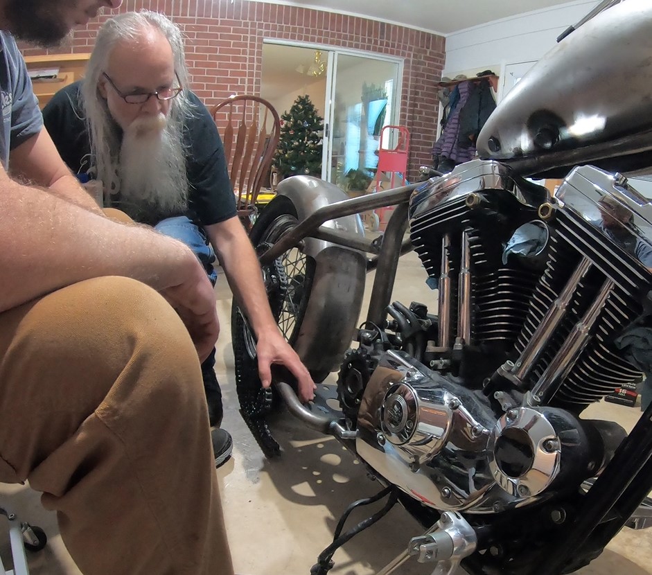
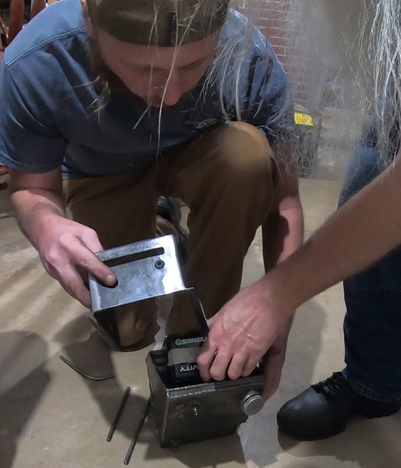
First thing we did was measure/place the oil tank, battery box, & rear brake master cylinder in place and see if there would be enough room for a chain tensioner.
Side note- I was going to try and get by without running a chain tensioner, however, Doc Flynn was over a couple of weeks ago (he's been building hardtails for decades), and he was absolutely sure I need one. He pointed out where even the smallest amount of slop on decel would end up ruining the paint on the fender cut out.
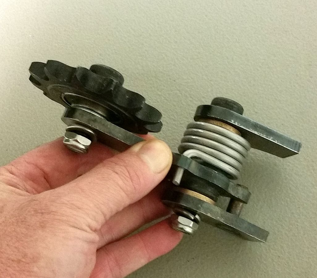
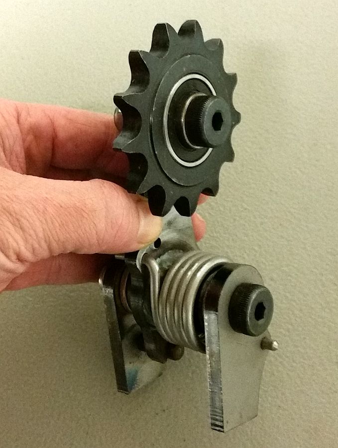
So, we are going with this chain tensioner...

...and it looks like, with some creativity...
...it's gonna be pretty tight...

...we will be able to fit it and still keep the M/C, oil tank, battery box and exhaust where we want.
Next up was revisiting the wiring.
Here is a diagram of the stock wiring-

Here is what we had it reduced down to originally-

And this is the new diagram we came up with yesterday.
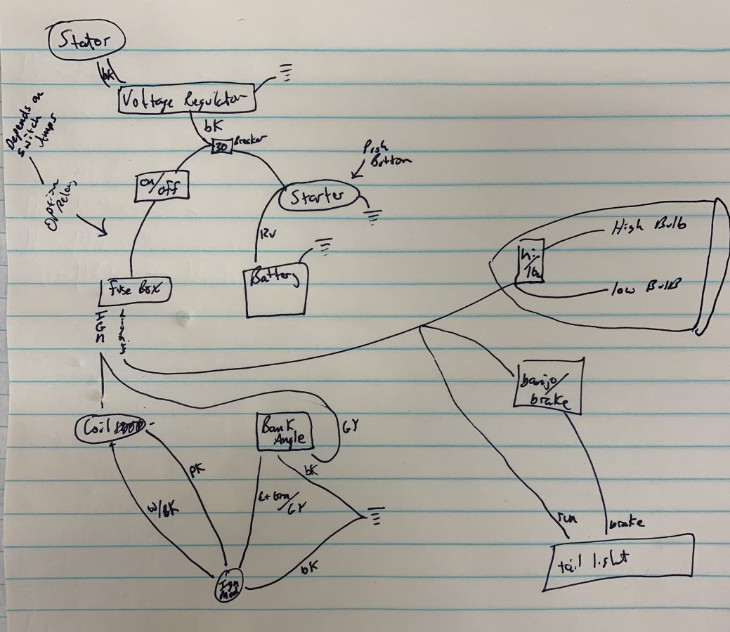
Even simpler!
Looking at everything with fresh eyes...

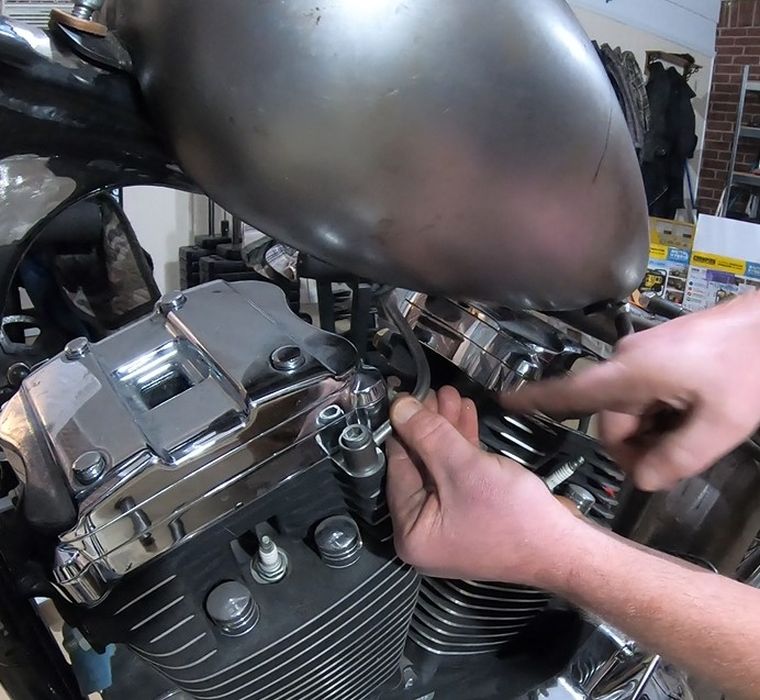
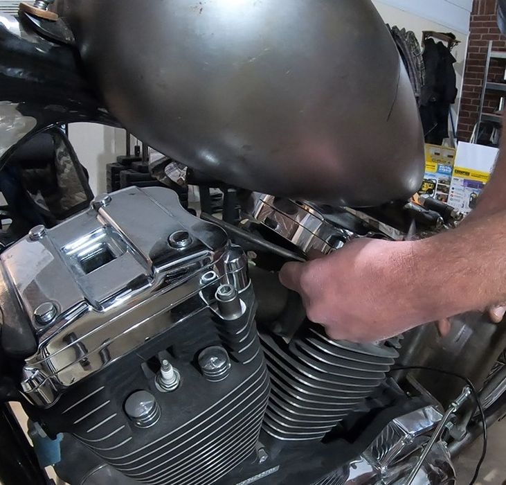
We will be ditching the bracket seen in the photo below, in favor of a billet bracket that we'll be cutting to go around the frame and around this coil.

Built into the bracket will be the on/off switch.
Whether we put the coil to the side of the frame tube (like pictured above) or to the front of the frame tube...that will be decided after we look at it both ways with everything else in place.
The other things we are working on...and if anyone has any input/ideas/photos/drawings, we welcome them...
1. We have two hydraulically actuated brake light switches, pictured below.
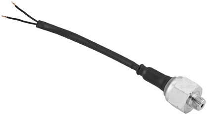
Goodridge 03-6939
We decided we did not like them. They are too big/bulky. We want to find something smaller to trigger the brake light when either the front or rear brakes are applied.
2. Still looking for the ideal front brake M/C-brake lever set up.
3. We are working on some design ideas for axle covers and a steering stem bolt. Any ideas welcome!
4. I need to choose some good looking battery cable. The run will be less than a foot for each the + & the -. I could go with plain black...but am entertaining other looks.
5. We are still deciding between modifying the stock shift and brake lever, buying some, or coming up with a nice design. Any ideas welcome!
6. The steering head is going to be quite open below the headlight, so we need to come up with a nice design for a neck badge.
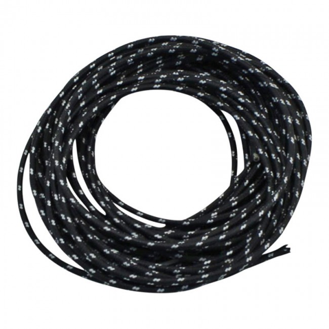
7. Need to locate the wiring to be used that will be visible...like wire to headlight. I'm thinking something like this.
There are a bunch of other little and big things, that we pretty much have nailed down. Just a matter of doing them.
Next week will be a short one, and the time on the SBS Chop will be spent mostly cutting stuff and getting things in order. Then week after next we will be on the actual bike installing.
Kevin
Time is still short, but we have a lot of motivation, so we're making the time!
First thing we did was measure/place the oil tank, battery box, & rear brake master cylinder in place and see if there would be enough room for a chain tensioner.
Side note- I was going to try and get by without running a chain tensioner, however, Doc Flynn was over a couple of weeks ago (he's been building hardtails for decades), and he was absolutely sure I need one. He pointed out where even the smallest amount of slop on decel would end up ruining the paint on the fender cut out.
So, we are going with this chain tensioner...
...and it looks like, with some creativity...
...it's gonna be pretty tight...
...we will be able to fit it and still keep the M/C, oil tank, battery box and exhaust where we want.
Next up was revisiting the wiring.
Here is a diagram of the stock wiring-
Here is what we had it reduced down to originally-
And this is the new diagram we came up with yesterday.
Even simpler!
Looking at everything with fresh eyes...
We will be ditching the bracket seen in the photo below, in favor of a billet bracket that we'll be cutting to go around the frame and around this coil.
Built into the bracket will be the on/off switch.
Whether we put the coil to the side of the frame tube (like pictured above) or to the front of the frame tube...that will be decided after we look at it both ways with everything else in place.
The other things we are working on...and if anyone has any input/ideas/photos/drawings, we welcome them...
1. We have two hydraulically actuated brake light switches, pictured below.
Goodridge 03-6939
We decided we did not like them. They are too big/bulky. We want to find something smaller to trigger the brake light when either the front or rear brakes are applied.
2. Still looking for the ideal front brake M/C-brake lever set up.
3. We are working on some design ideas for axle covers and a steering stem bolt. Any ideas welcome!
4. I need to choose some good looking battery cable. The run will be less than a foot for each the + & the -. I could go with plain black...but am entertaining other looks.
5. We are still deciding between modifying the stock shift and brake lever, buying some, or coming up with a nice design. Any ideas welcome!
6. The steering head is going to be quite open below the headlight, so we need to come up with a nice design for a neck badge.
7. Need to locate the wiring to be used that will be visible...like wire to headlight. I'm thinking something like this.
There are a bunch of other little and big things, that we pretty much have nailed down. Just a matter of doing them.
Next week will be a short one, and the time on the SBS Chop will be spent mostly cutting stuff and getting things in order. Then week after next we will be on the actual bike installing.
Kevin
DK Custom Products
Sponsor
- Thread starter
- #188
I was over in the shop earlier.* Devin had just started the drawing in the Fusion 360 software for the billet coil holder.
It will have a cut-out for this on-off switch in it.

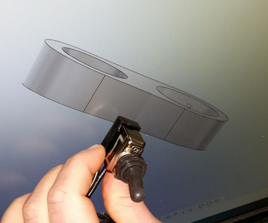
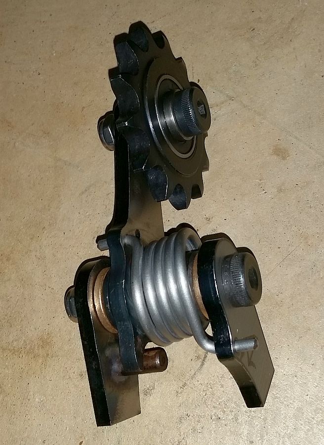
We also received the chain tensioner in the mail today...
...Friday we will be working on the bike again, and one of the things will be figuring out what modifications will be needed for the weld-on ears.
*Kevin
It will have a cut-out for this on-off switch in it.
We also received the chain tensioner in the mail today...
...Friday we will be working on the bike again, and one of the things will be figuring out what modifications will be needed for the weld-on ears.
*Kevin
Looks like brainstorming 2.0 ... ... and I'm loving it.
... and I'm loving it.TonkaDriver
450+ Posts
Coil Vibration
Will you be doing anything to dampen the vibration to the coil?
I was over in the shop earlier.* Devin had just started the drawing in the Fusion 360 software for the billet coil holder.
It will have a cut-out for this on-off switch in it.
*Kevin
Will you be doing anything to dampen the vibration to the coil?
DK Custom Products
Sponsor
- Thread starter
- #191
Will you be doing anything to dampen the vibration to the coil?
Yes, good catch! One, or probably both, of the inner diameters will be cut large enough to accommodate a silicone dampening sleeve.
Kevin
DK Custom Products
Sponsor
- Thread starter
- #192
Got a bit more done yesterday, we are back to making steady headway!
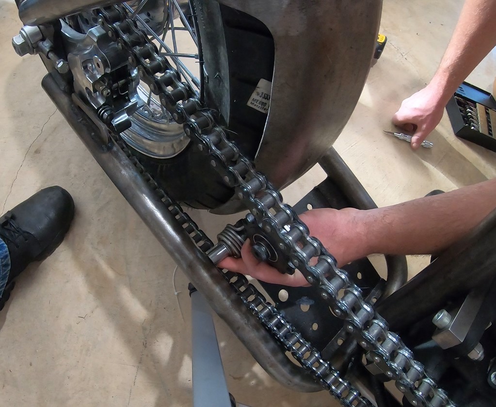
First thing was to look and see how to fit the pulley guard over the sprocket and chain-
Since they stick out further than the pulley and belt, we are marking where we are going to have to grind some metal away for clearance-

Outside, on a wet towel...

...if the chrome gets too hot it will discolor, so between the soaking wet towel and frequent spray-downs...

...we get it ground down enough...

...that after several test fitting, everything clears.

Time to bolt it up with the Master Cylinder and roll it around a bit to ensure we have the clearance...
More in next post.
Kevin
First thing was to look and see how to fit the pulley guard over the sprocket and chain-
Since they stick out further than the pulley and belt, we are marking where we are going to have to grind some metal away for clearance-
Outside, on a wet towel...
...if the chrome gets too hot it will discolor, so between the soaking wet towel and frequent spray-downs...
...we get it ground down enough...
...that after several test fitting, everything clears.
Time to bolt it up with the Master Cylinder and roll it around a bit to ensure we have the clearance...
More in next post.
Kevin
DK Custom Products
Sponsor
- Thread starter
- #193
After getting the cover and master cylinder in place, we now know exactly how much room we have to work with for the chain tensioner.
There is not a lot of room...
...First Try...

...maybe back here...nope...
...back up front, near the front sprocket again...

...we spent a bunch of time trying different locations, talking about what would and would not work. Conclusion- we are going to re-fabricate the weld-on tabs that came with it and and tack it up close to the front sprocket and make sure everything clears.
Hard to tell from the photo's, but it is very close to the frame rail on one side and to the oil tank on the other.
Last thing we looked at was the brake arm and clutch arm (shift arm).
We have 3 choices:
1. Modify the stock pieces
2. Design & Fab some from scratch
3. Find some to purchase
Here we are messing with one design...

The other thing we talked about...since the shifter is going to be the clutch pedal, I will probably want a "peg" that is larger than normal to enable better control over the clutch friction zone....And we want the clutch and brake pegs/pedals to match. So there's that to think about too when deciding on arm design.
That's all we did on the bike yesterday.
*********************
My current "to do" list is:
Decide on clutch and brake arms.
Come up with a re-design of the top motor mount.
Get some more pieces from Bung King for above.
Come up with a design for the Steering Stem Bolt, and one that will also be able to be used on axle covers.
Get the switch and indicator lights installed in the headlight bucket.
Order misc. cable, wire & hose.
Devin is working on the billet coil and switch mount.
Kevin
There is not a lot of room...
...First Try...
...maybe back here...nope...
...back up front, near the front sprocket again...
...we spent a bunch of time trying different locations, talking about what would and would not work. Conclusion- we are going to re-fabricate the weld-on tabs that came with it and and tack it up close to the front sprocket and make sure everything clears.
Hard to tell from the photo's, but it is very close to the frame rail on one side and to the oil tank on the other.
Last thing we looked at was the brake arm and clutch arm (shift arm).
We have 3 choices:
1. Modify the stock pieces
2. Design & Fab some from scratch
3. Find some to purchase
Here we are messing with one design...
The other thing we talked about...since the shifter is going to be the clutch pedal, I will probably want a "peg" that is larger than normal to enable better control over the clutch friction zone....And we want the clutch and brake pegs/pedals to match. So there's that to think about too when deciding on arm design.
That's all we did on the bike yesterday.
*********************
My current "to do" list is:
Decide on clutch and brake arms.
Come up with a re-design of the top motor mount.
Get some more pieces from Bung King for above.
Come up with a design for the Steering Stem Bolt, and one that will also be able to be used on axle covers.
Get the switch and indicator lights installed in the headlight bucket.
Order misc. cable, wire & hose.
Devin is working on the billet coil and switch mount.
Kevin
DK Custom Products
Sponsor
- Thread starter
- #194
We've Not been sitting on our hands the last couple of weeks regarding the SBS Chop.* Just nothing picture worthy.
We came up with a design we're happy with for the top motor-mount.
Got our bungs in from Bung King.
Still tossing around sketches for the steering stem bolts and axle covers.
Got the front brake control from Brian, gonna try and make it work.* (thank you Brian!)
Spent a crazy amount of time looking for some clear covered battery cables.* Finally got some ordered yesterday....and it's only quasi clear.**
Sort of getting ahead of myself, but did spend a bit of time on powder and paint this last week.* The reason I say ahead of myself....we are going to put this together, ride it for a bit to make sure everything is how we want.* After that, blow it apart for powdercoating of the frame and some misc. parts, and painting of the tins.
Right now I'm leaning toward an Alien metal flake Silver for the powder coating.**
This weekend we'll be carrying one of the welders to the house to get the chain tensioner in place, and tack up the new motor-mount design.
Kevin
DK Custom Products
Sponsor
- Thread starter
- #195
Spent a bunch more time on the chop this weekend.
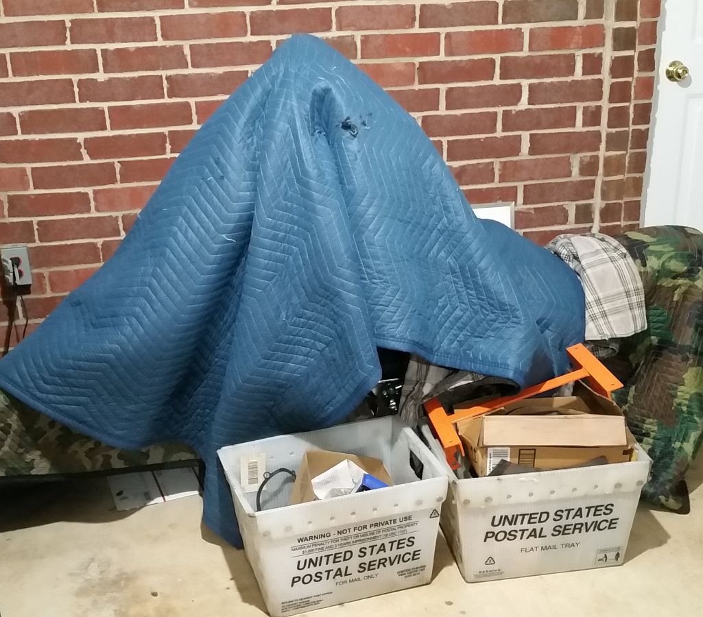
Pulled her out from under the blankets, and away from the wall.

I'll tell you up front, we carried the welder from the shop to the house, but did NOT even unload it.
We thought we would pull the pulley guard and then weld the tensioner in place.

That is when the frustration began...
...we brought some extra stock to weld the tensioner in place...
...but no matter how we tried configuring it, we could not get everything to fit.

We spent over 2 hours trying to get the frame, the tensioner, the chain, the oil tank and the rear fender to play nice together.

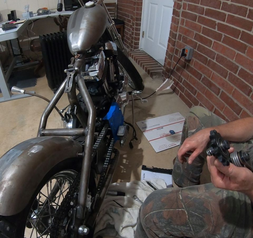
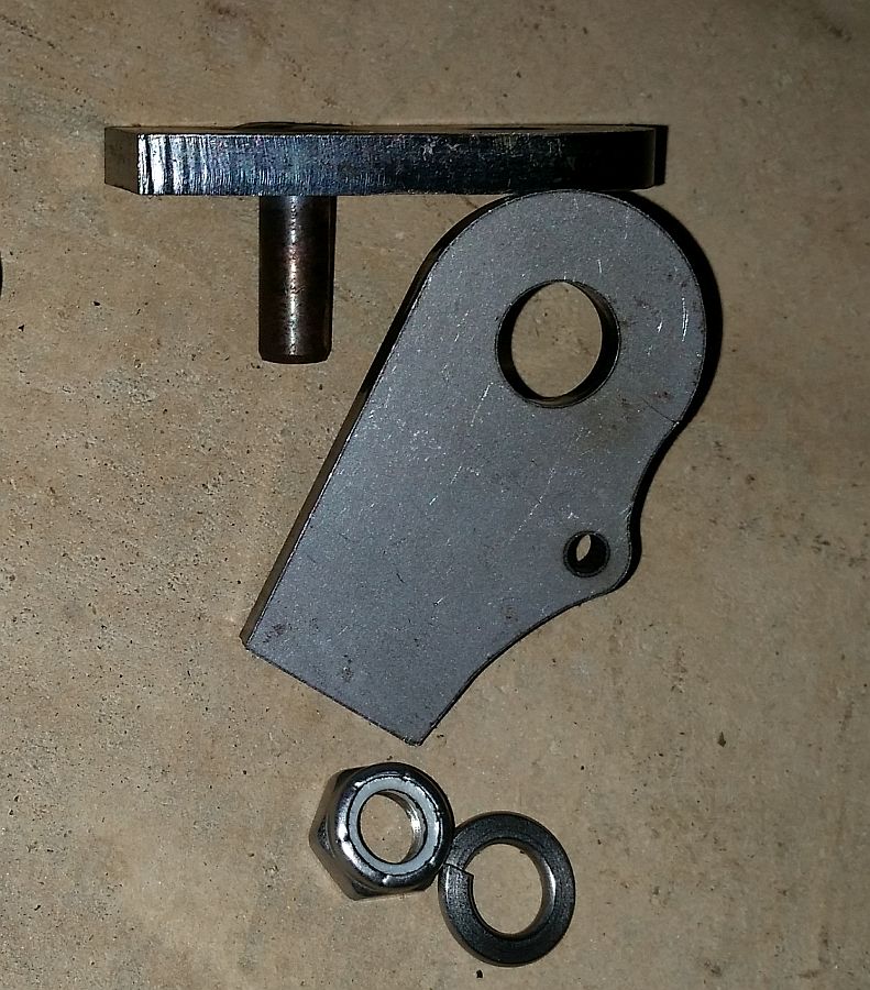
These legs are what came with the tensioner. We've looked at how to reshape them, make our own...nothing is coming together.
Talked about running no tensioner, but I don't want to ruin the paint on the fender.
The problem is the oil tank/battery holder. It is taking up almost all the space between the frame rails, leaving nowhere to mount the tensioner.
I even briefly started thinking about going the more traditional route of putting a typical tank up higher...then I had an idea...finally!
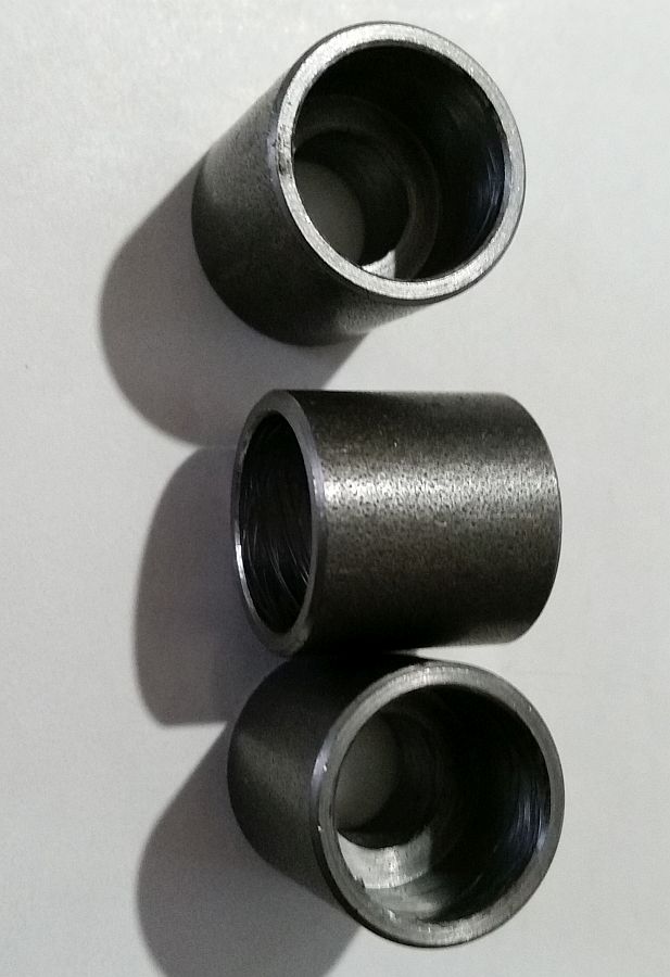
Ditch any variation of the legs completely and...

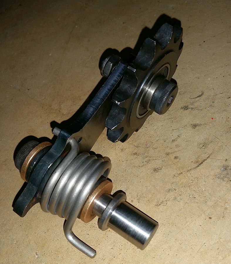
...use a threaded bung that we'll weld into the frame.
We can weld a little tab on the frame for a stop for the other side of the spring.
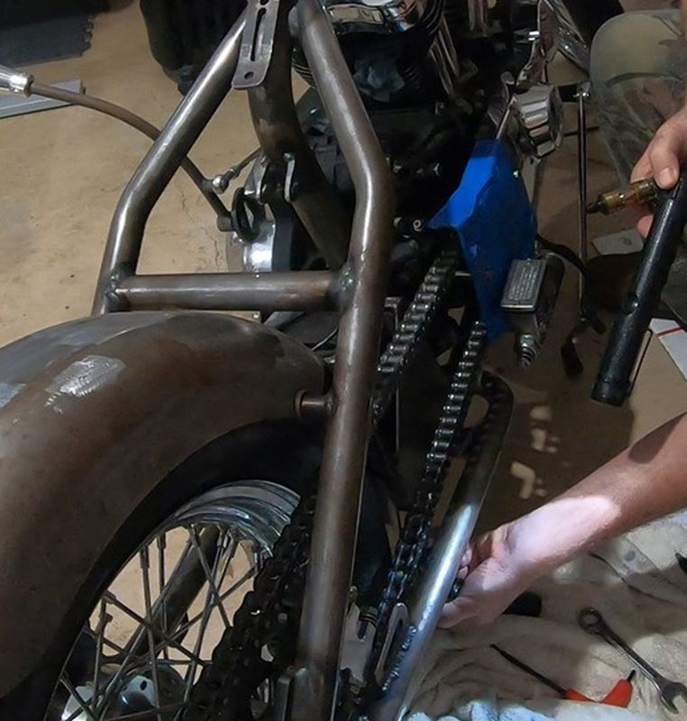
But we still had a problem. We do not want to have to remove the oil tank just to get to the tensioner bolt. There is still no room, even for that. Putting the tensioner here will give less than 1/2" between the bolt head and the side of the tank.
More in next post.
Kevin
Pulled her out from under the blankets, and away from the wall.
I'll tell you up front, we carried the welder from the shop to the house, but did NOT even unload it.
We thought we would pull the pulley guard and then weld the tensioner in place.
That is when the frustration began...
...we brought some extra stock to weld the tensioner in place...
...but no matter how we tried configuring it, we could not get everything to fit.
We spent over 2 hours trying to get the frame, the tensioner, the chain, the oil tank and the rear fender to play nice together.
These legs are what came with the tensioner. We've looked at how to reshape them, make our own...nothing is coming together.
Talked about running no tensioner, but I don't want to ruin the paint on the fender.
The problem is the oil tank/battery holder. It is taking up almost all the space between the frame rails, leaving nowhere to mount the tensioner.
I even briefly started thinking about going the more traditional route of putting a typical tank up higher...then I had an idea...finally!
Ditch any variation of the legs completely and...
...use a threaded bung that we'll weld into the frame.
We can weld a little tab on the frame for a stop for the other side of the spring.
But we still had a problem. We do not want to have to remove the oil tank just to get to the tensioner bolt. There is still no room, even for that. Putting the tensioner here will give less than 1/2" between the bolt head and the side of the tank.
More in next post.
Kevin
DK Custom Products
Sponsor
- Thread starter
- #196
Even with the threaded bung as the anchor, there is still the fitment issue, until we realized that there is about 1" between the back of the oil tank and the fender.
That will be enough room for access to the tensioner bolt. FINALLY!

Wow, that was a PITA. But we will bring the welder back again, along with a couple of good bits and the laser, and get that installed.
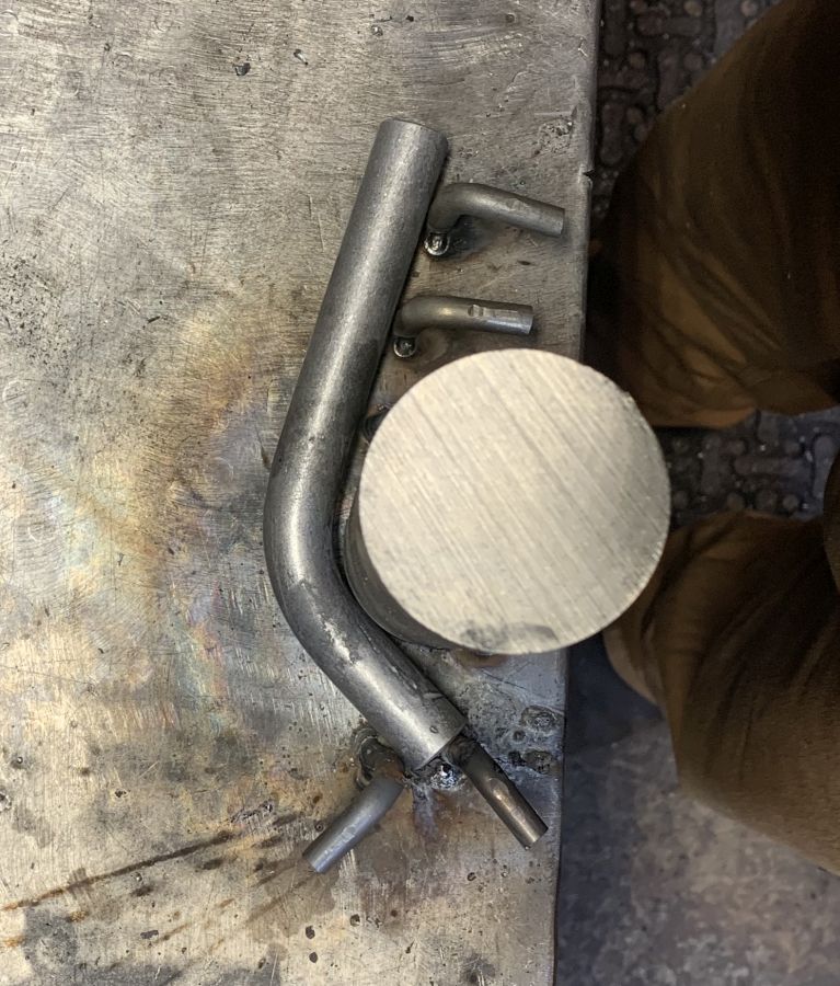
Moving on to the motor-mount.
We got some bungs in...
...and brought some small rod to form for a template for the larger stock that we'll make the actual motor-mount out of.
The curved stock will go from the bung to above the intake manifold...

...off of both heads. The ends will be cut at a 45 on each, then welded together.
This will give us rigidity from the frame, behind the tank, to both cylinder heads. It will also be clean and simple, which is the look I'm going for.
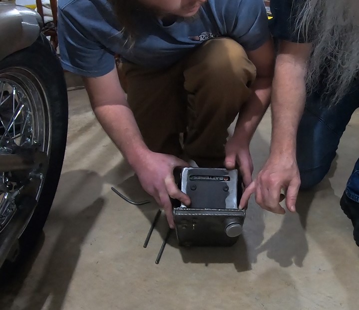
Next up was deciding how to attach the battery cover...
...to the oil tank. Gonna slot the cover, weld 4 small studs to the tank, and there will be 4 nuts. All hidden unless looking for them with a flashlight.
Back covered up, against the wall, til next week.
Did not get nearly as much done as we thought we would....but after almost giving up on the tensioner, it feels like a lot, now that we got it figured out.
Kevin
That will be enough room for access to the tensioner bolt. FINALLY!
Wow, that was a PITA. But we will bring the welder back again, along with a couple of good bits and the laser, and get that installed.
Moving on to the motor-mount.
We got some bungs in...
...and brought some small rod to form for a template for the larger stock that we'll make the actual motor-mount out of.
The curved stock will go from the bung to above the intake manifold...
...off of both heads. The ends will be cut at a 45 on each, then welded together.
This will give us rigidity from the frame, behind the tank, to both cylinder heads. It will also be clean and simple, which is the look I'm going for.
Next up was deciding how to attach the battery cover...
...to the oil tank. Gonna slot the cover, weld 4 small studs to the tank, and there will be 4 nuts. All hidden unless looking for them with a flashlight.
Back covered up, against the wall, til next week.
Did not get nearly as much done as we thought we would....but after almost giving up on the tensioner, it feels like a lot, now that we got it figured out.
Kevin
peteg59
Meme Master
Glad you were able to get er done so to speak, but do you really need a tensioner?
I guess if you feel the chain side? clearance isn't right to prevent damage to the fender, it's worth the effort you've invested to cure the issue.
At least you made forward progress this weekend, regardless how many items you were able to check off your hitlist...
Progress is progress and there's still many more weekends to get this finished, until comfortable riding season starts up again.:clapping:
DK Custom Products
Sponsor
- Thread starter
- #198
Glad you were able to get er done so to speak, but do you really need a tensioner?
I guess if you feel the chain side? clearance isn't right to prevent damage to the fender, it's worth the effort you've invested to cure the issue.
At least you made forward progress this weekend, regardless how many items you were able to check off your hitlist...
Progress is progress and there's still many more weekends to get this finished, until comfortable riding season starts up again.:clapping:
If I was meticulous about keeping the chain tight I might not need a tensioner. However, if on a trip, I don't want to have to stop every couple of hours and check the chain and adjust it if necessary...and just missing one time could slap it up against the painted fender.
I would cut out more of the fender if I could, but have to leave the mounting point where it is on the frame rail.
Yes, I am grateful to even be able to build this...just got ants in my pants to get it done.
Oh, btw, it was 65* this morning on the ride into the shop!
Kevin
DK Custom Products
Sponsor
- Thread starter
- #199
This last Monday, Devin and I had 4 hours scheduled to work on the chop...but first we had to do a "little" test on a new product we've been working on for a couple of months.
5 hours later, our "little" test was done, and we are redesigning some aspects of it. Will be doing a 500 mile test on it in a couple of weeks when the new prototype is cut.
Anyway, we are going to be working on it again this afternoon...for sure, this time. lol
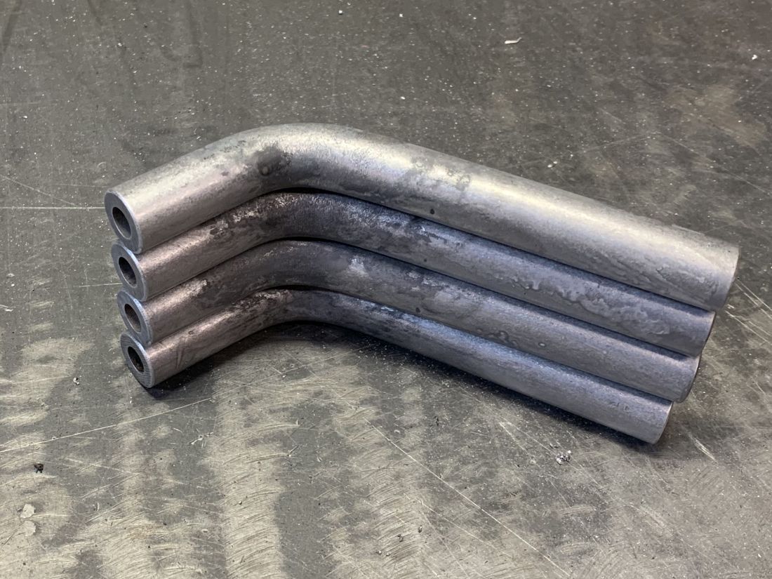
We took the small material that we hand bent last time for the motor mount, and made a jig-
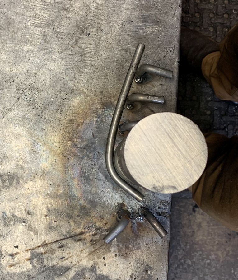
We then took the actual material, 3/4" OD DOM, and heated it up and bent it to the shape we want-
We only need two of them, but went ahead and shaped four of them. We still need to cut the ends at a 45 and concave out the opposite ends for the bung. So we have a couple of extras, just in case.
Not going to do any welding today, but some drilling, cutting, and working on the exhaust.
Kevin
5 hours later, our "little" test was done, and we are redesigning some aspects of it. Will be doing a 500 mile test on it in a couple of weeks when the new prototype is cut.
Anyway, we are going to be working on it again this afternoon...for sure, this time. lol
We took the small material that we hand bent last time for the motor mount, and made a jig-
We then took the actual material, 3/4" OD DOM, and heated it up and bent it to the shape we want-
We only need two of them, but went ahead and shaped four of them. We still need to cut the ends at a 45 and concave out the opposite ends for the bung. So we have a couple of extras, just in case.
Not going to do any welding today, but some drilling, cutting, and working on the exhaust.
Kevin
DK Custom Products
Sponsor
- Thread starter
- #200
Friday afternoon we took off to work on the chop.
We did not bring the welder this week...we'll be fitting, cutting and brainstorming, so next time we bring the welder over we'll have a bunch to do.
First up was to size & cut the 45's on the motor mounts...

...it took about 1.5 seconds for us to realize we had bent the wrong stock. It was supposed to be .5" OD, not the .75" OD that we bent.

We already removed the jig from the welding table, so we'll be tacking it back up and bending the correct stock next week.
Next up was getting the tensioner located and hole in the frame drilled for the bung.
This is where we want it...
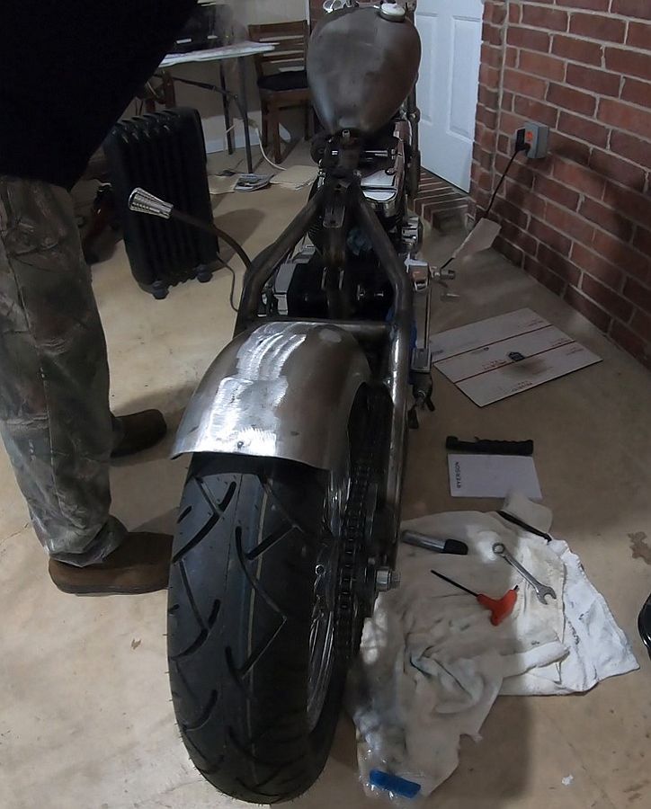
...right between the back of the oil tank/battery box and the front of the rear fender.
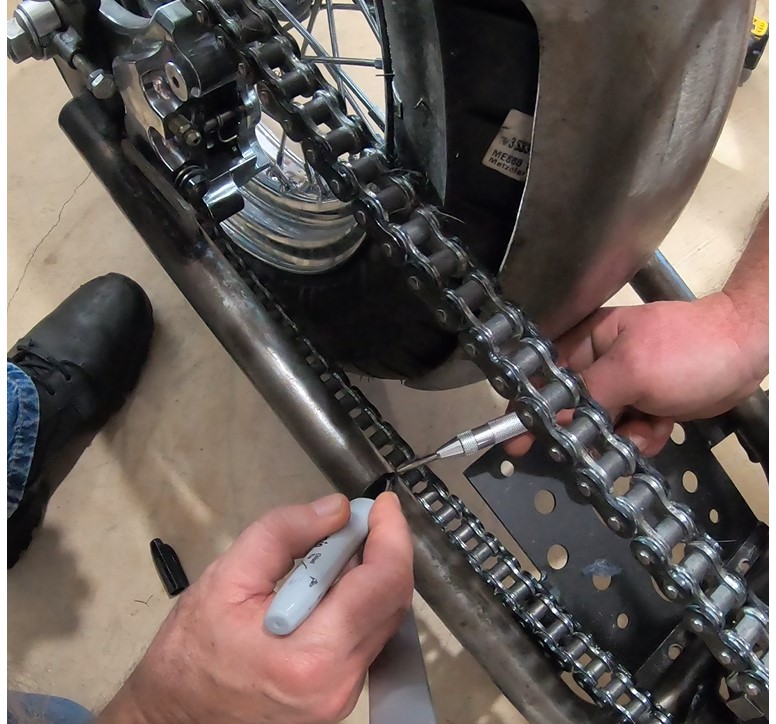
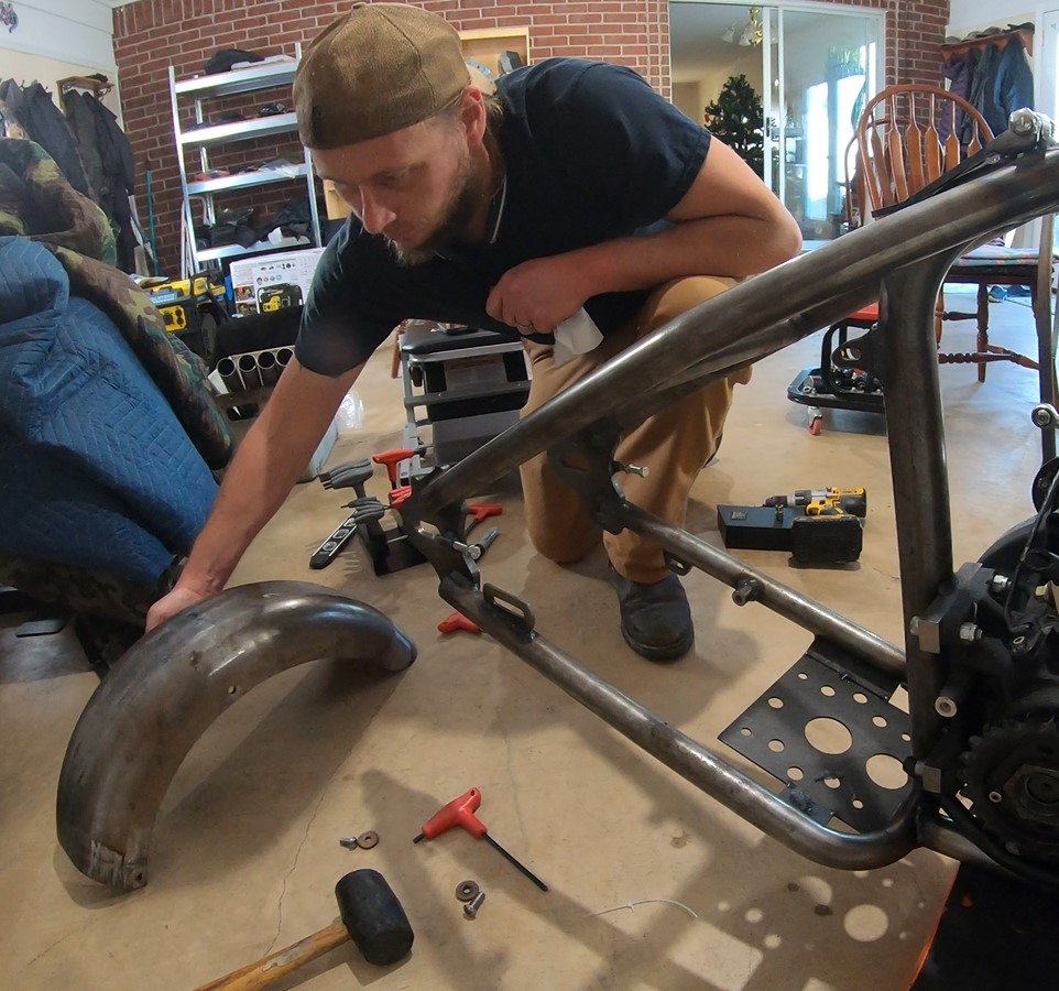
After marking the location, we need to remove...
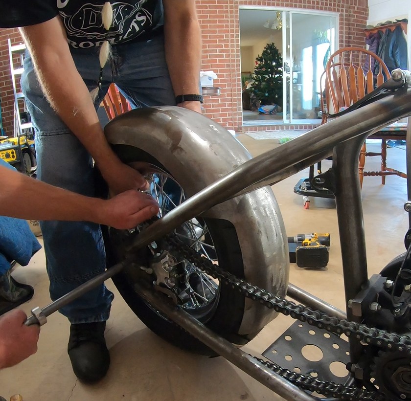
...the rear tire & brake caliper...

...so that we can get to the rear fender...

...and get it out of the way, so that we can drill the hole for the bung.
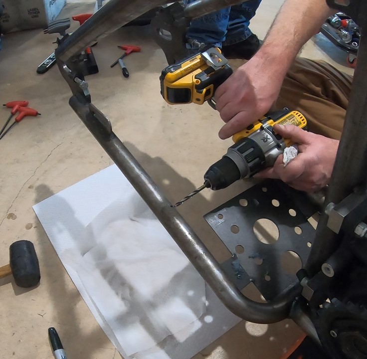
Time to drill the pilot hole in the frame!
More in next post.
Kevin
We did not bring the welder this week...we'll be fitting, cutting and brainstorming, so next time we bring the welder over we'll have a bunch to do.
First up was to size & cut the 45's on the motor mounts...
...it took about 1.5 seconds for us to realize we had bent the wrong stock. It was supposed to be .5" OD, not the .75" OD that we bent.
We already removed the jig from the welding table, so we'll be tacking it back up and bending the correct stock next week.
Next up was getting the tensioner located and hole in the frame drilled for the bung.
This is where we want it...
...right between the back of the oil tank/battery box and the front of the rear fender.
After marking the location, we need to remove...
...the rear tire & brake caliper...
...so that we can get to the rear fender...
...and get it out of the way, so that we can drill the hole for the bung.
Time to drill the pilot hole in the frame!
More in next post.
Kevin
Welcome to the Trike Talk Community
Join our vibrant online community dedicated to all things Trikes! Whether you're a seasoned rider or just starting out, this is the place to share experiences, tips, and stories about your three-wheeled adventures. Explore modifications, maintenance advice, and rides, all while connecting with fellow trike enthusiasts from around the globe
Forum statistics
Trike Talk Community
Welcome to a community dedicated to the most diverse and fastest growing powersports segment, Motorcycle Trikes. Come join the discussion about the best makes and models, popular modifications and proven performance hacks, trike touring and travel, maintenance, meetups and more!
Register Already a member? LoginForum statistics