


Nice! The liquid tape is a good idea.


 Likes: 4
 Thanks: 3


Hello, I thought this was going to be an easy modification to do, all so that I wouldn’t have to look down at my speedometer to see the LED indications “distracting”.
First I hit up VTX discussion websites to see if someone had already did this and to see how they did.
Not finding anything by searching old posts, I put out a post for help:
Normal line of site of warning lights, no looking down!
This did get a few, helpful hints, and even one person that had done something similar to what I was trying to do. They gave me some information on what they remembered which was very beneficial. THANK YOU!
So on to my latest mod:
First I went on EBay ordered a bunch of different color LED’s to install (around $5.00), to the upper part of my batwing fairing. I got plain water resistant LED’s (didn’t know exactly how they would work out). EBay also has LED’s that have displays such as (arrows, fuel pump, ect…) maybe later I’ll swap them out, they are bit more pricy though.
I also ordered up a couple of water resistant multi-connection connectors to be able to easily disconnect the batwing from the bikes wiring too.
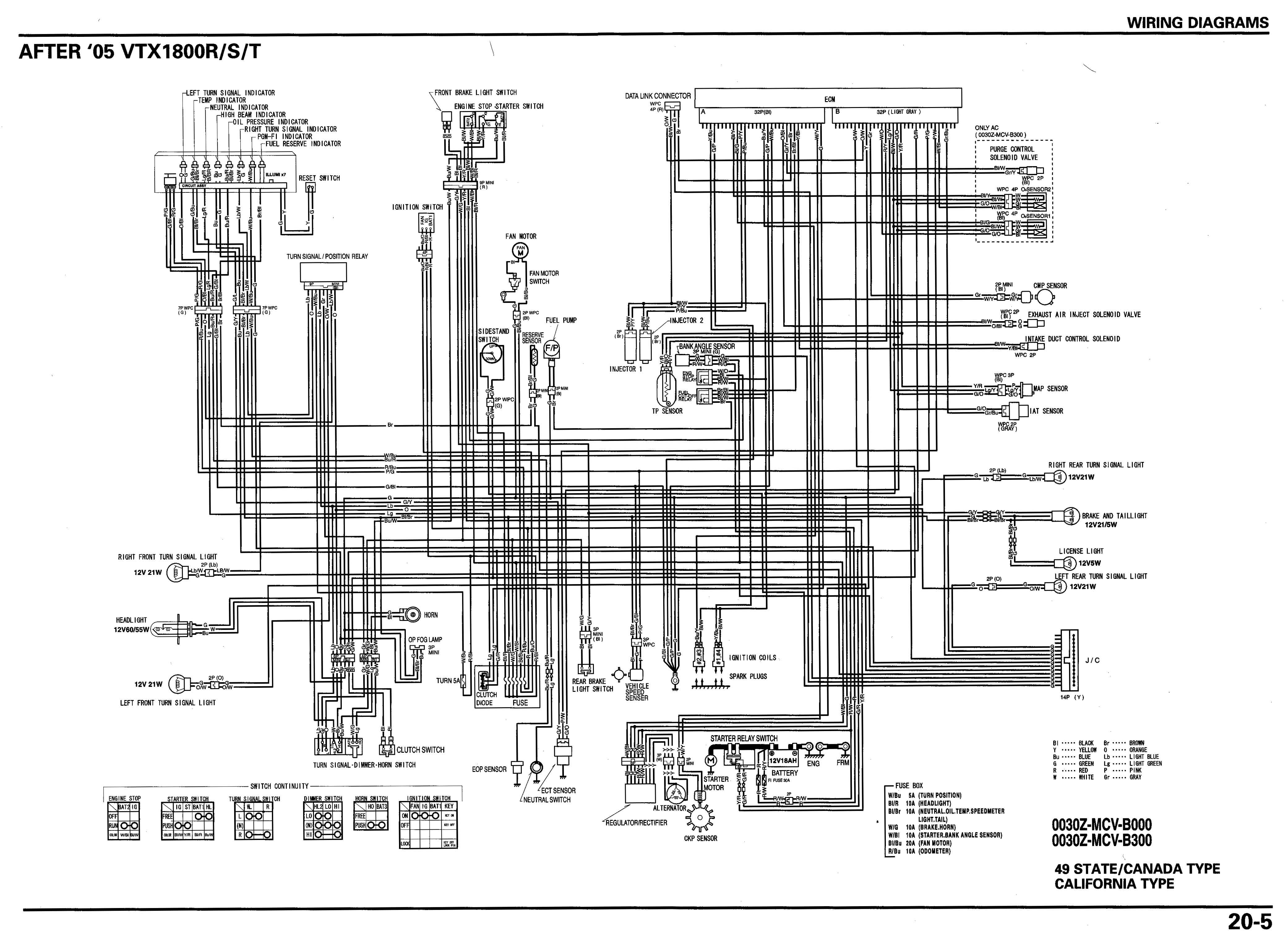
Next I needed to dig out my Clymer repair manual so I could follow the wiring diagram for my 2006 1800S. This was a problem is it shows color coded lines that are very hard to tell what each color line is with many of them having two colors on them.
Luckily I found a copy on https://tech.bareasschoppers.com/ that had words for the colors rather than the colors themselves this was a god send.
When the LED’s came in I dug right in, pulled the seats, and gas tank so I could get to the wiring.
BIG NOTE:
The LED’s have a Red and Black leads (wires) on them to indicate normal polarity Red +, and Black -
I made a an (LED test cable) to check the wires and connections, I soldered a sewing needle to one leg (input) of an LED, on the other leg first I put an inline fuse (to protect my bikes wiring) and then I soldered a sewing needle on end of the wire. I’ll include a picture, you know “worth at thousand words and all”.
I had a pretty good idea where I wanted to tie into the wiring harness; I picked the bike side of the two connectors of the wiring leads bundles going to the speedometer (the wires look to be about a size 18 or 20).
I used my (LED test cable) to check and insure I have the right cable by first poking one of the sewing needles thru the insulation of one of the wires (using the wiring diagram as a guide).
Well for the most part everything went pretty well, although there are several similar colored wires in each wiring leads bundles.Next issue is that some of the LED’s on the speedometer are reverse fed: where you’re not adding a positive signal to complete the circuit to light the LED, but, instead adding a negative signal to complete the circuit. 1. Anyway as I identified each wire I would strip the top of the insulation of the wire back about ¼”, then use a small screwdriver to reach in between the insulation and the wire and put a bend in it.
2. Next I would strip back ¼” on the end of the wire I am tagging in, next forming it into a J and slipping it under the opening in the other wires insulation.
3. Next I soldered them together, covered with liquid tape (a kind of rubber seal), finely when dry would wrap with electrical tape.
I mounted the LED’s in a piece of aluminum and pop riveted to my radios mount. I was never able to get the temperature LED to work correctly, no matter if I put a positive or negative on the remote LED, the LED would light up (which really has me scratching my head) so I gave up on that one.Below are photos of pretty much everything, I am happy the way it turned out, just wish it had been a bit easier.
David Hilton Ret. ETC/SS


Nice! The liquid tape is a good idea.
Nice work David.
With regards to the temp sensor, you will probably have to attach the remote LED to the internal TEMP LED leads inside the instrument housing to get proper operation. This is because the TEMP indicator is probably driven by a comparative circuit. This means that the voltage signal supplied by the thermistor TEMP sensor is compared to a reference voltage inside the Control Circuit shown in the schematic. If the sensor voltage is below the reference voltage the TEMP LED stays off. If the sensor voltage is above the reference voltage the TEMP LED comes on. Here is a link to a typical circuit: http://www.learningaboutelectronics....r-circuits.php
Connecting an external LED across the TEMP sensor leads may affect the voltage level seen by the OEM comparative circuit and adversely affect the operation of the OEM TEMP indicator.
My suggestion would be to look at the possibility of mounting an additional OEM TEMP sensor by piggy backing or teeing off the original original sensor if possible (I'm not familiar with you motorcycle) and building a simple comparative circuit like the one shown to drive the external TEMP LED.
Another option would be to get something like this: https://www.ebay.com/itm/Digital-W12...h_Q77TZsOwhezg
With this module you could mount the sensor somewhere close to the OEM sensor, set the trip point temp, and use the relay output to drive the external TEMP LED. Put the module in a waterproof enclosure (you don't need the display except for setup) and tuck it up out of sight. Put the module in a clear waterproof box and mount it up top somewhere if you want a display. It only reads out in Celsius but once you know where normal temp is, who cares?
This module only goes to 110C / 230F. There are other modules like this out there with different temp ranges. Also, these cheap Chinese modules are cheaper than collecting the discrete components and building it yourself!
Who knew that you would become an engineer just by riding your motorcycle?
Good ideas,
Comparative circuit is possibly inside the speedometer housing (no prints available to check), but, I'm not going to guess.
And the link to the remote temp gauge would work but it's a very big display.
As far as piggy backing on the speedometer mounted LED, this is not an easy fix ether as the whole unit is sealed.
I have been told that the Honda VTX's never overheat, so, I am going to just have the tank mounted light for that.
Thanks for the advise,
David Hilton Ret. USN ETC/SS
Originally Posted by vwbug72501

Note: Changes or modifications to original equipment (bike) configuration have not been approved or tested by the factory.
If you attempt or make modifications to your equipment, the responsibility is yours for any damage to your equipment, as well as any required testing and safety issues are yours alone.
This post is for informational purposes only, and is for entertainment.

David... I wondered why I haven’t seen you post much since joining TrikeTalk.
You have been one busy person!
These guys love DIY projects - especially so well documented as to detail.
New course heading Mr. Sulu: ...2nd star to the right and straight on til morning...!!
Scooter and Sassi....2 furrever.
Posting Permissions


