DK Custom Products
Sponsor
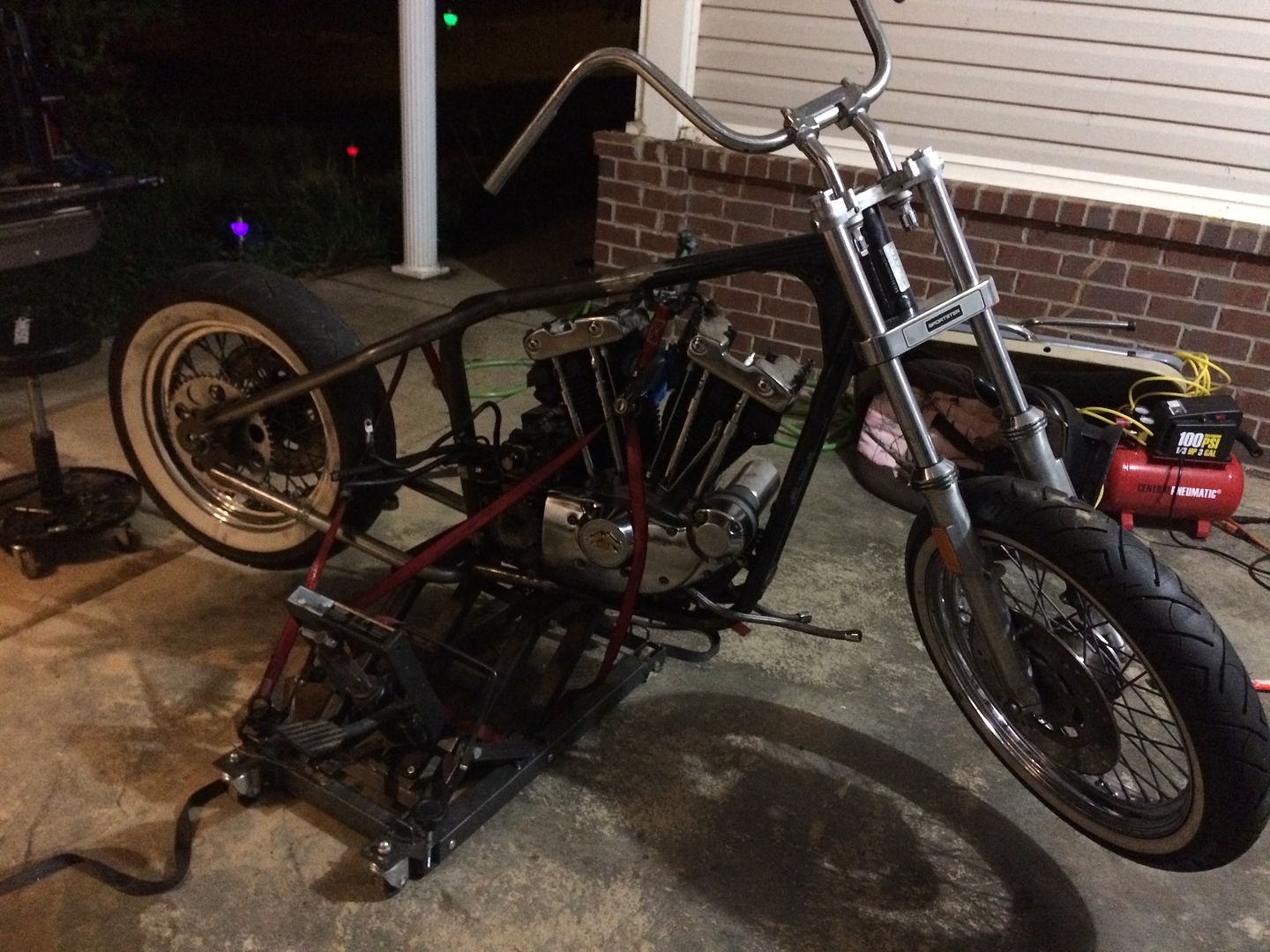
- Thread starter
- #121
They look good in black KevinThumbUp
Added plus for black is they can be "touched up" easier than chrome, after a pavement scraping session through the twisties.
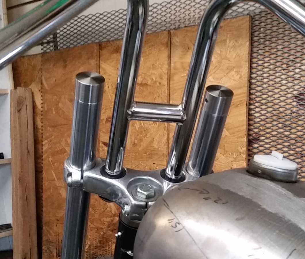
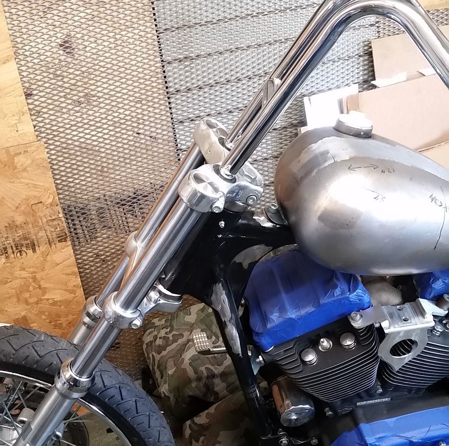
Yeah, I like them in black on the DK Sporty...on the SBS Chop I think they are going to look really good in chrome.
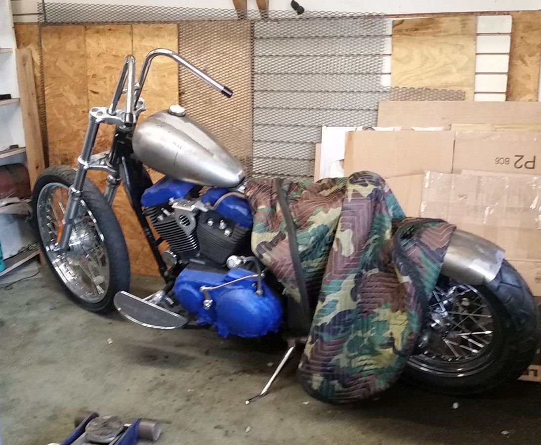
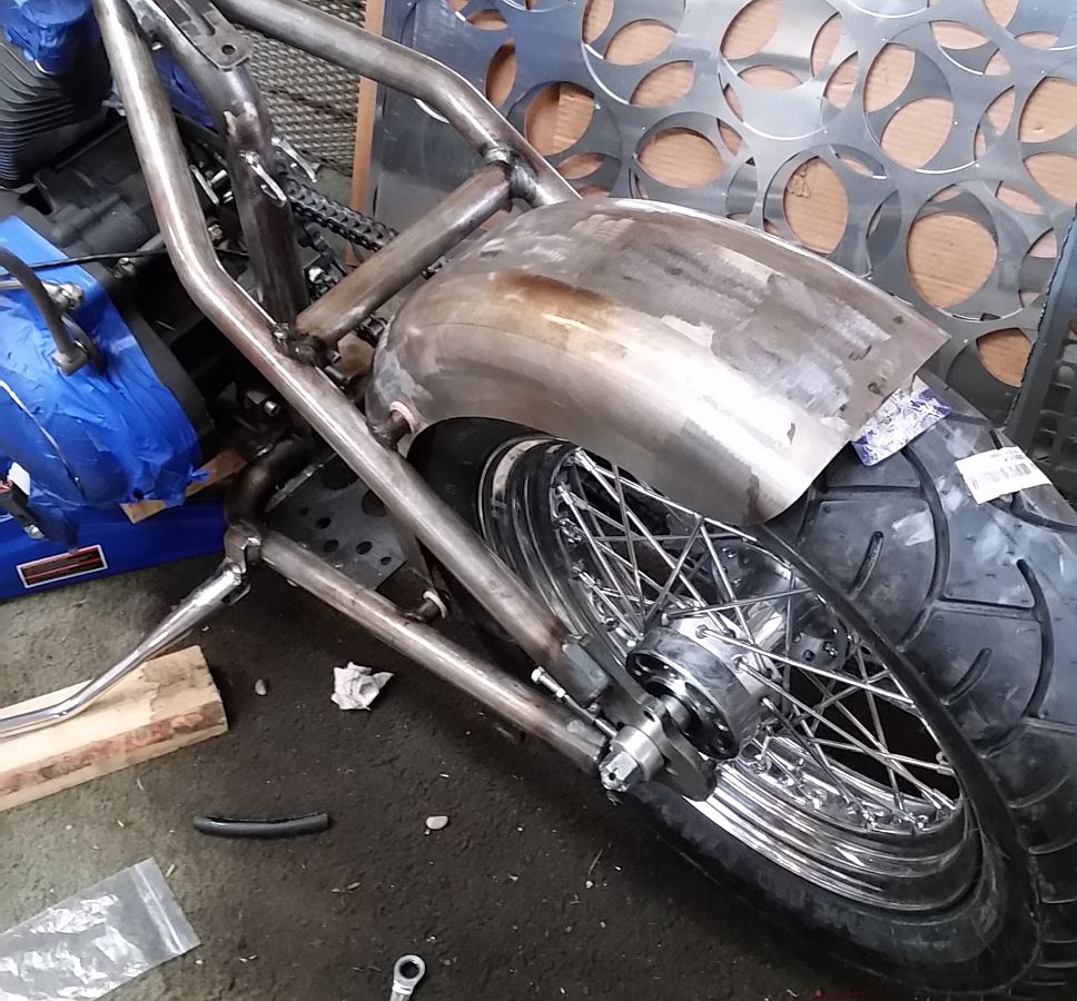
I don't know if I am going to be scraping them at all. The lean angle is much greater with these than with the stock pegs....also, it is much more than the pegs/heel rest combo I was running on the DK Sporty.
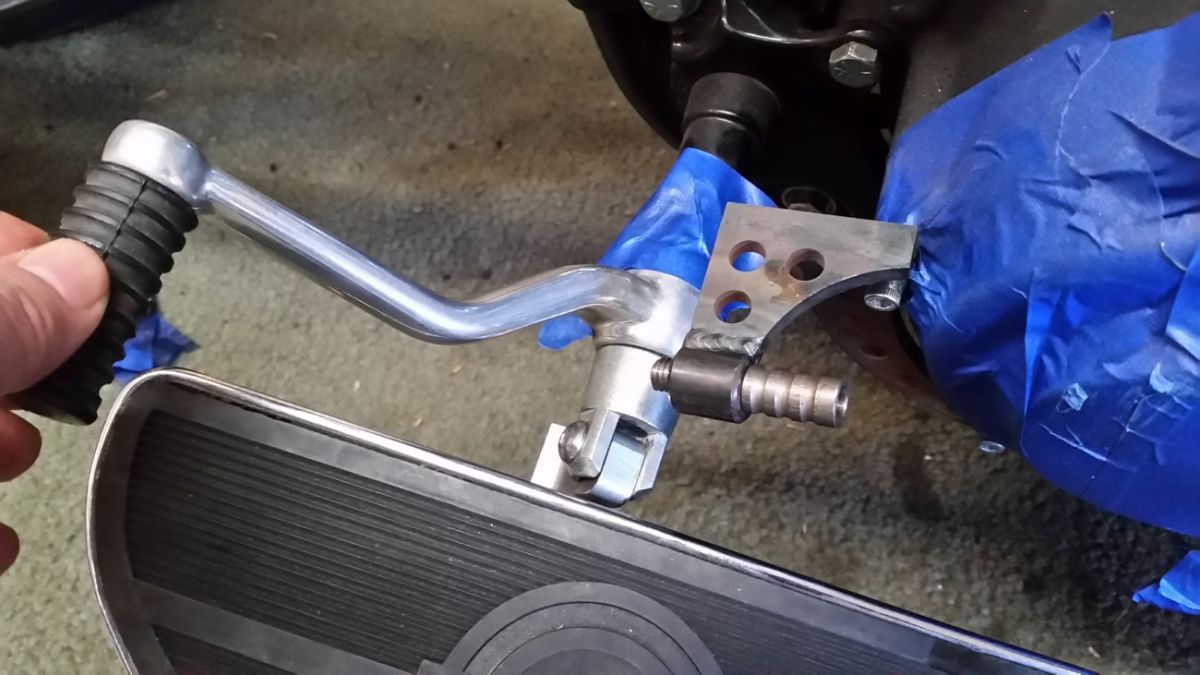
Some of our low profile pegs can't be scraped in the twisties either...but for comfort on long distance riding, I almost always am running the heel rests...which end up scraping. (see pics below)
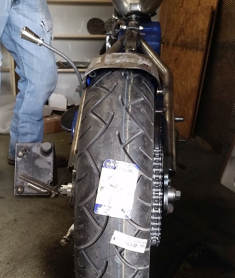
In the few days I have been riding with these floorboards I have leaned over trying to scrape....have not been able to so far. I think I will run out of tire/or scrape something else before these floorboards will scrape.
")
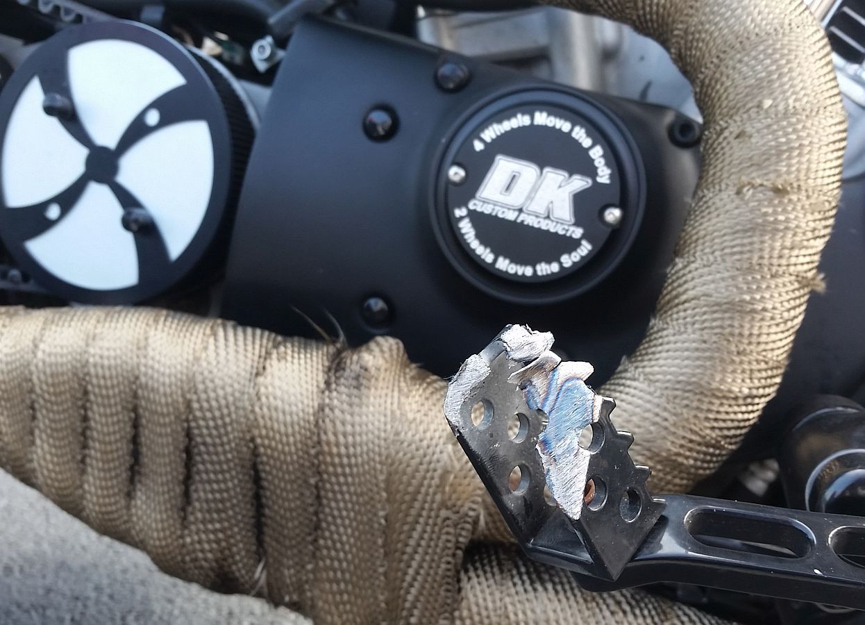
This is the right side heel rest ground down pretty good after some riding in the Smokeys-
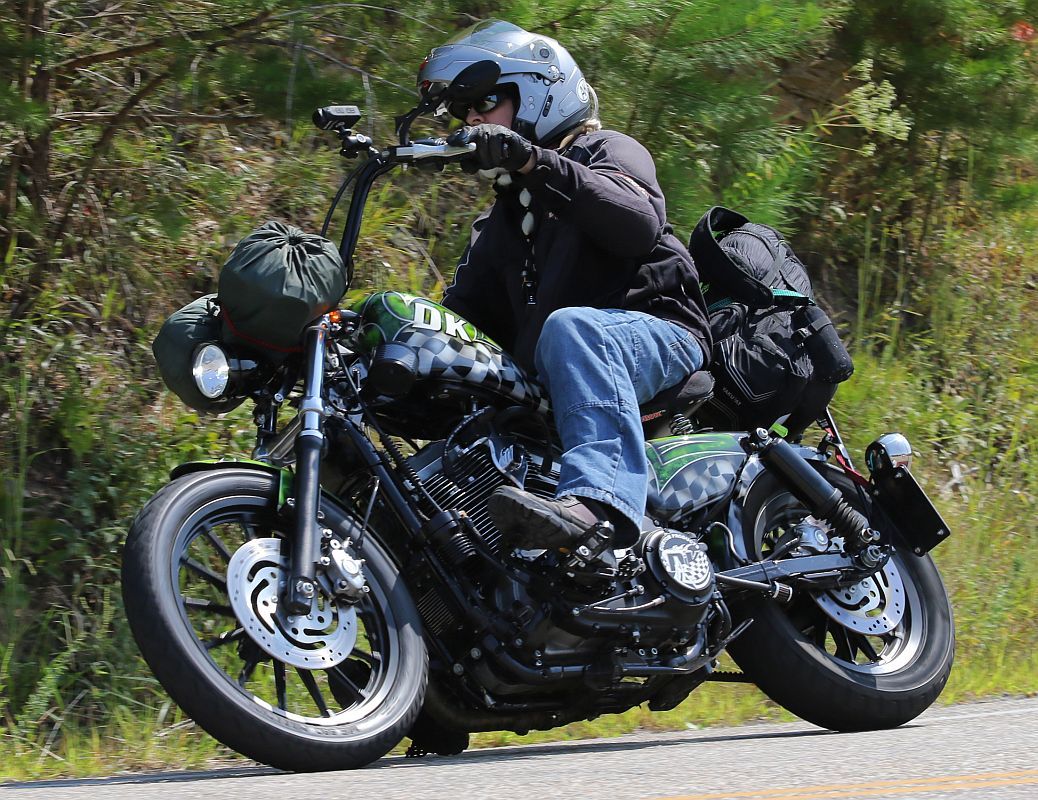
You can see the right side heel rest touching down in this pic-
Kevin